- At 09-14-20 14:30:39
- E36 318Ti Build
- 22RPD Staff
- Read Time: 2 minute read
E36 318Ti Build: Turbo Mounting
When it comes to turbocharger setups, the possibilities are nearly limitless, but some choices can make the endeavor more or less of a challenge. One of the first questions that must be answered is whether the turbo will be a 'top mount' or 'bottom mount'. Let's begin by discussing some of the benefits and drawbacks of each option:
Top Mount
Pros:
- Flex-Factor, the turbo and downpipe will be very visible which can be a heavy influence for show oriented builds
- Ease of access to turbo, and more space for larger setups Natural oil drain
Cons:
- Increased engine bay temperatures
- Exhaust in close proximity to other components (hood, valve cover, electrical, etc)
- Weight is biased high and far forwards
Bottom Mount
Pros:
- Streamlined exhaust routing
- Tighter packaging and shorter runners (Faster spool)
- Weight is biased as low as possible and closer to the center of the car
Cons:
- Turbo is minimally visible from above (could be a pro or con)
- Potential oil drain issues (may require a scavenge pump to properly drain)
- May require a turbo specific engine mount arm
Retaining the air conditioning with a turbo setup in an E36 chassis is possible regardless of top or bottom mount, and the difficulty in doing so depends on the exact setup (manifold/turbo/pipe routing). Many of our top mount builds retain AC by using our custom lines and fittings which route along the passenger edge of the engine bay.
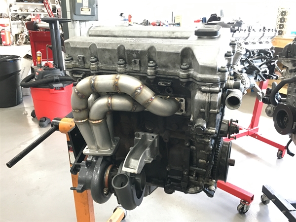
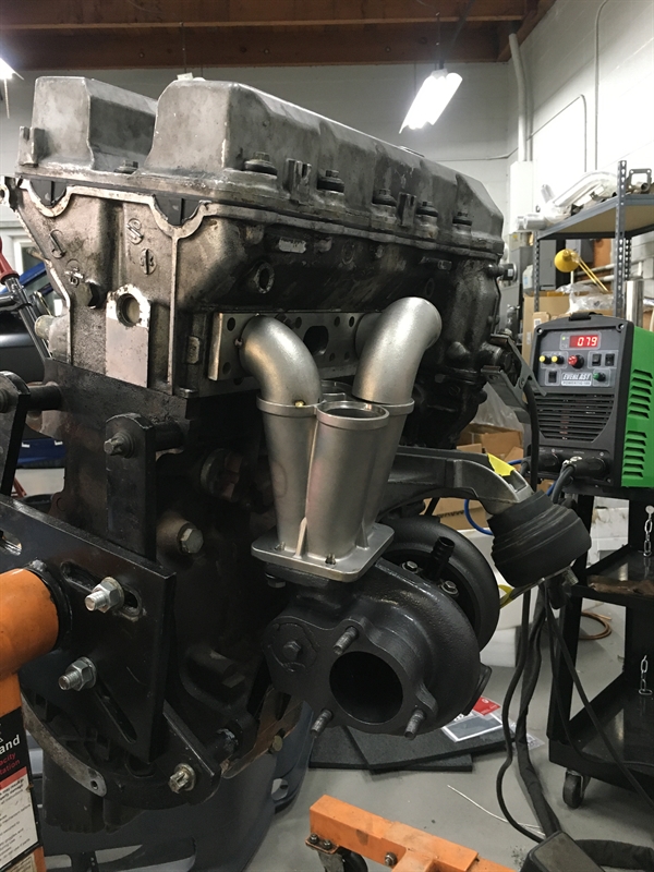
The cover photo leaves no surprise here, but I have chosen to run a bottom mount setup for the 318ti. My objectives for this car in order of importance are to be as lightweight/balanced as possible, as fast as possible, and as unsuspecting as possible. Overall, the benefits of hiding the turbo down low lend themselves perfectly to my goals and desires.
First thing's first, I need to acquire all the materials needed to create a turbo manifold. The essentials are as follows:
- M42 4cyl head flange (I simply cut 2 cylinders off of an M5x 6cyl head flange)
- T3 flange and collector (This piece was from Ebay and transitions smoothly from each pipe to the turbo)
- 304L stainless steel pipe (I used off the shelf bends and straight sections of 1.5" schedule 10 pipe)
- A spare engine to use as a reference/jig for fabrication
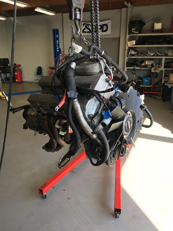
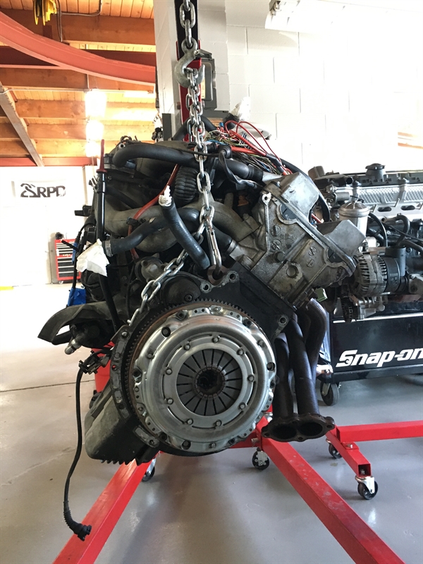
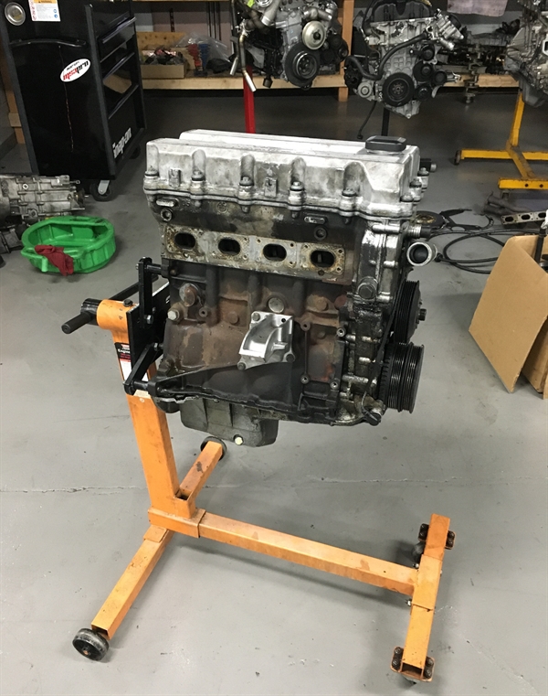
I picked up a complete running M42 w/ 250G transmission, and quickly got to work stripping it down:
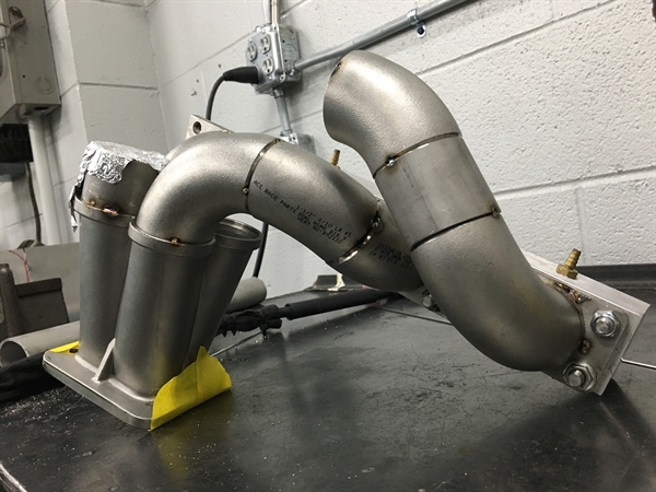
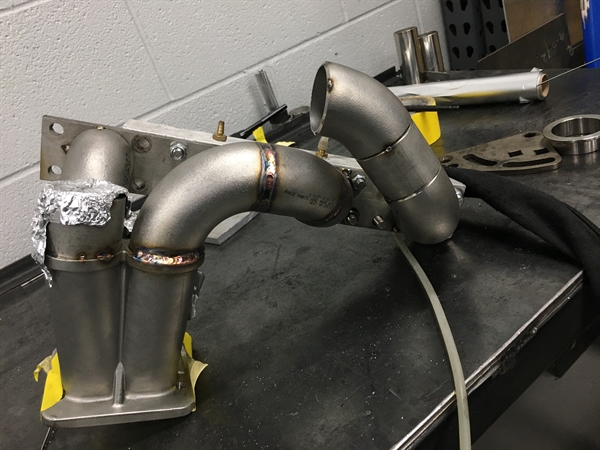
It all begins with a couple of tack welds:
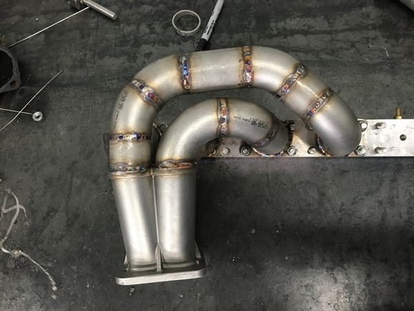
When welding pipes together like this, it is very important to consider the strength of the entire assembly. We used a process called 'back-purging' for the remainder of the fabrication. For those who are familiar with welding, the machine's nozzle projects a shield gas which isolates the weld pool from oxygen and other contaminants in the air. Without any shield gas, the weld is prone to porosity which can significantly reduce its strength.
'Back-purging' completely fills the inside of the manifold with the same shield gas, protecting both sides of the weld and resulting in a manifold that will not crack and fail over time.
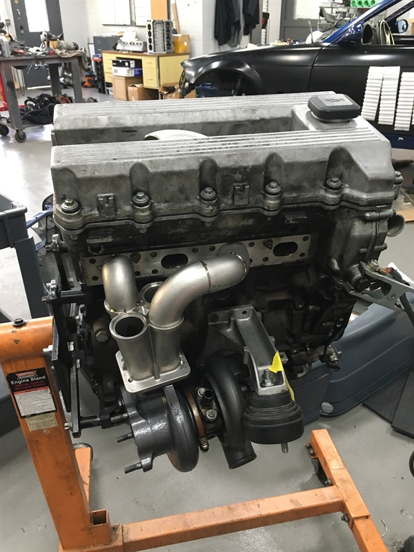
Now that this unit is fully welded, let's bolt it back onto the engine! :D
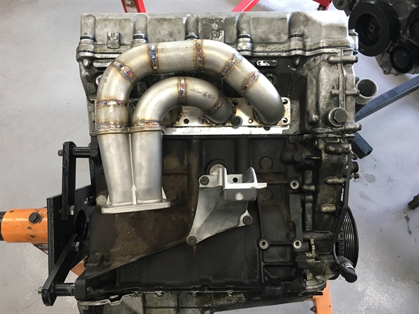
Why stop there, when it really belongs on the car? :O

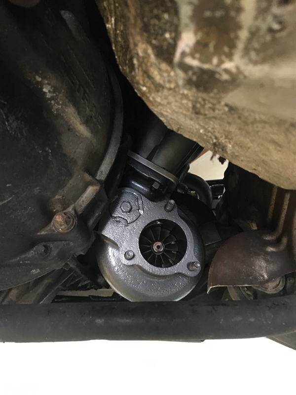
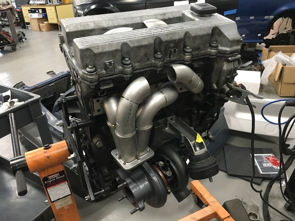
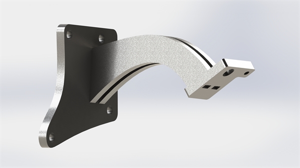
I have found that in order to properly clock the turbo compressor housing to its final position, I need just a little bit more clearance out of the engine mount arm. To make things much easier, I designed a high-arch/low profile arm out of 3/8" stainless steel.
I'm looking forward to sharing the next stages of this project with you, stay tuned!
-E